Measuring thermal conductance of a component or a thermal subsystem shouldn’t be a big mystery, right? In principal, the thermal conductance (C) of a component is really just heat flow and temperature (C = Q / ∆T). So, what makes this measurement tricky? Well, where errors are often made are with the assumptions that heat is contained and accounted for accurately and that temperature measurements are not all that critical with respect to location. The reality is that both heat flow and temperature measurements do require a high level of consideration, if accurate thermal conductance characterization is important.
Let’s take for example a copper thermal strap used to cool an optical system through a cryocooler interface. In this particular case, the strap thermal conductance must be within ten percent on either side of the design point to achieve optimum system performance. If thermal conductance of the strap is not properly characterized through accurate component testing, once installed in the system the temperature dependent heat lift from the cryocooler may cause the optical system temperature to drift outside the established control band and compromise detector performance. So, it is equally important to verify the thermal strap performance through testing as it is to be able to accurately design a strap to meet a well defined specification.
First, it is critical to know whether the specified thermal conductance is inclusive of the interfaces at both strap ends. (Incidentally, this is a whole other topic that merits an individual future article.) For this case, we will assume that the specification is for the thermal strap only. Thus, the natural inclination would be to instrument the strap with temperature sensors at both ends to determine the temperature differential across the device with the steady-state heat flow.
Here is where the potential problem creeps in; assuming that the terminals (end fittings) of a thermal strap are isothermal can be a faulty (but less than obvious) assumption, even if they are copper or aluminum. Simply taping or bonding temperature sensors on the surface of the strap terminals will not suffice because those sensors will not be directly in the heat flow path. More often than not, there will be some thermal gradient within the end fittings themselves, in particular if the thermal strap is highly conductive between the interface locations.
Since imbedding a thermal sensor in the strap end fittings is not typically an attractive option, we solve the sensor location issue with our calibrated test interface blocks that feature imbedded temperature sensors just adjacent to the thermal strap interfaces, whether the strap is clamped, bonded, or bolted (we highly recommend matching the test thermal interfaces as closely as possible with the actual application interfaces).
With the temperature sensors directly in the heat flow path, we are getting an accurate measurement of the thermal gradient exactly where the heat is being transported. If, as in this case, we are interested in determining just the strap thermal conductance alone, we can subtract the joint thermal conductance contributions since we have excellent characterization of these interfaces from literature sources, our own testing, and years of prior experience. Furthermore, if the thermal test configuration accurately replicates the customer’s interfaces, the direct measurement includes interface losses and there may be no need to know the strap thermal conductance separately.
Figure 1 illustrates this thermal strap example and the testing methodology that provides the most accurate thermal conductance measurement results, along with some typical terms we use in collecting data and in interpreting and reporting results.
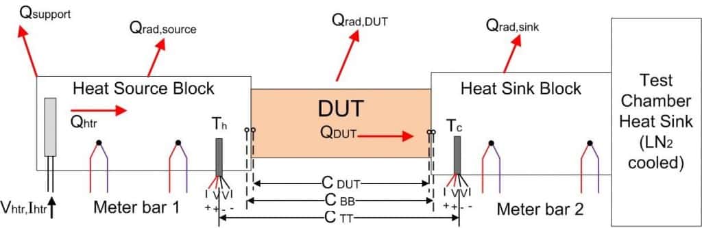
In this illustration:
Qhtr = Heat energy generated by the heater
QDUT = Heat energy flowing through the Device Under Test (DUT)
Qsupport = Heat leak through the bracket used to mount the heat source block.
Qrad,source = Heat leak by radiation to/from the heat source block
Qrad,DUT = Heat leak by radiation to/from the DUT
Qrad,sink = Heat leak by radiation to/from the heat sink block
Th = Temperature measured in the heat source block near the interface
Tc = Temperature measured in the heat sink block near the interface
CTT = Measured thermal conductance between temperature measurement points
CBB = Calculated thermal conductance between the test block surfaces
CDUT = Calculated thermal conductance between the DUT end fitting surfaces
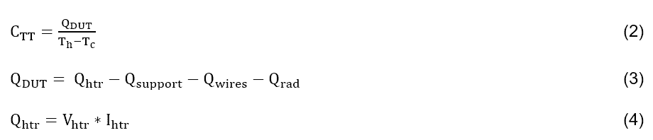
Thermal conductance is the heat flowing through an object divided by the temperature drop it takes to drive that flow:

The problem with measuring QDUT and ΔTDUT directly is that we would need a way to measure heat flow and temperature of the thermal strap itself right at the DUT-test block interface.
Many labs that test thermal conductance simply tape temperature measurement devices to the ends of the DUT to measure temperatures. The engineers at TSL have a lot of experience with this, enough to know that this is not a reliable way to measure temperatures.
To ensure accurate measurements, we measure temperatures inside the test blocks, in the heat flow path, just under the mounting surface (CTT). From there it a simple calculation to account for the thermal resistance through the test block to the surface of the test block under the DUT (CBB) and account for the mounting interface (CDUT).
The heat flow through the thermal strap (QDUT) is simply the heat dissipated by the heater, and subtract out all of the losses.
The following is a very simplified version of the calculations.
which are measured. The heat leaks and temperature gradients are calculated using combinations of conduction and radiation heat transfer, found in any heat transfer textbook:
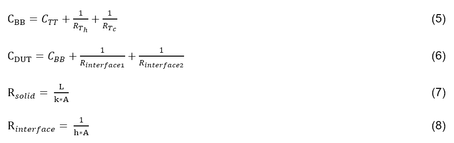
The value of h is important when one wants to determine the thermal strap conductance alone.
In addition to calculating QDUT from equation (3), the heat source and sink blocks are used as meter bars. This makes the testing compliant in accordance with ASTM E1225. These blocks are calibrated so that measuring temperature difference across the blocks provides an accurate method to calculate heat flow, confirming QDUT. Unless reasonable agreement is achieved between the calculated heat flows, thermal conductance results will not be valid.
Typically, CBB and CDUT are both reported results. CBB is reported because it is the actual measured value, accounting for the test setup, and is the performance that you can expect if the same strap mounting technique is used (TIM, bolt torque, etc.).
CDUT is a deduced value and is reported when there is the desire to know how the strap itself performs, perhaps because the interfacing method is not defined or there is ample margin due to interface thermal resistance already built into the thermal system design and therefore it is CDUT that is specified in the procurement document.
Like any other engineering discipline, it makes sense to be detail oriented when specifying and performing thermal validation testing in any situation where you rely on thermal performance in your system.