Graphite Fiber Thermal Straps: Risky and Obsolete – Part 2
Don’t Risk Your Project by using Graphite Fiber Thermal Straps
This post is based on an article written by the engineers who were the first to develop and validate graphite fiber thermal straps for thermal management applications in several domestic and foreign aerospace programs.
This is the second of a three-part segment. In Part 1, we covered the most basic material properties of pitch-based graphite fiber, namely stiffness and fiber fracture tendency. We explained how these material properties were very limiting in terms of design and the risk created with using the graphite fiber in thermal straps.
In this segment, we cover specific properties of high thermal-conductivity graphite fiber that are less obvious, but equally important to introducing risk in thermal systems.
Graphite Fiber Dynamic Stiffness
Dynamic stiffness is defined as the frequency-dependent ratio of the dynamic force to the resulting dynamic displacement. In complex mechanical systems it can be difficult to relate dynamic stiffness to static stiffness (which is much easier to measure). Such is the case with graphite fiber thermal straps where the dynamic stiffness is many orders of magnitude larger than static stiffness. In Part 1 of this article, we discussed the high impulse force needed to flex the bundles of graphite fiber that comprise a thermal strap. The large dynamic stiffness exhibited by graphite fiber thermal straps is essentially due to these same effects. In the dynamic environment, forces are either cyclical or random and only applied for a fraction of a second. This results in very different behavior as compared with a static force and displacement, when fibers can realign and distribute stress to take a new positional form. Simply put, the rapidly shifting force in the dynamic environment is on a much smaller time scale than it takes to overcome impulse force and the resulting fiber realignment in the graphite fiber thermal strap.
Why is this important for thermal straps? There are two primary reasons:
The first is that in space systems, the launch induced forces are highly dynamic and frequency dependent. To some extent, the same can be true in aeronautical systems and even ground-based systems that are on the move. If only static stiffness is measured and considered in the design, the forces imparted at the thermal strap interfaces will be greatly underestimated during the dynamic modes. The result can be damage to sensitive components or even complete failure.
The second reason is that thermal straps are often used to move heat across mechanically isolated boundaries. Such is the case in a cryocooler vibration isolation system where the intent is to dampen vibration from a compressor or displacer to the extent that exported forces can’t disrupt optics, sensor or detector performance. Because graphite fiber thermal straps have such a high dynamic stiffness, they are not useful for thermal management in vibration isolation applications.
Graphite Fiber Contact Forces in Thermal Straps
As you might imagine, inter-fiber contact forces in a graphite fiber thermal strap, where there are often millions of fibers bundled together, can be quite involved and complex in terms of how mechanical flexibility is impacted. However, in general there are two categories of forces prevalent: friction forces and chemical forces.
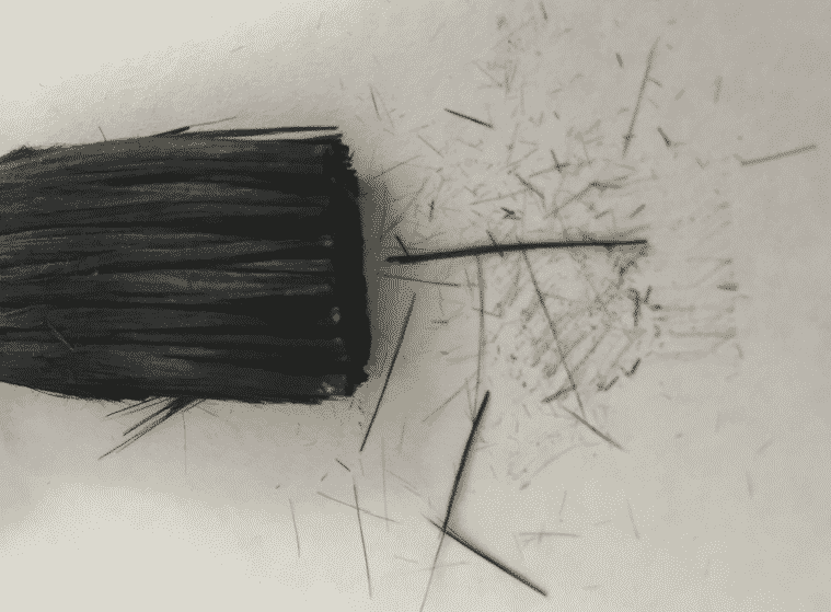
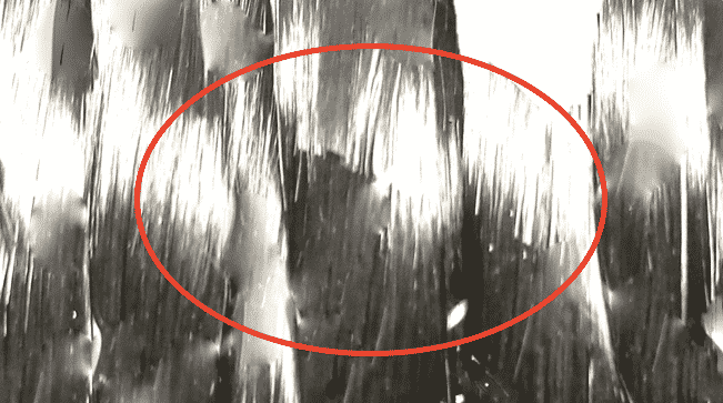
Friction forces are those that are due to the natural roughness on the surface of the drawn fiber. When adjacent fibers need to move relative to each other, there is a frictional resistance as some fibers interlock at the surface. Consequently, this is sometimes the mechanism that leads to fiber fraying and resulting particle contamination.
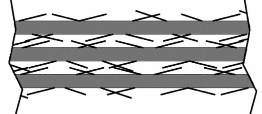
Figure 1. Graphite fibers have rough surfaces leading to significant friction forces.
Chemical forces are due to weak but not insignificant electron bonding that takes place between adjacent fibers. Per the manufacturer of high-conductivity graphite fiber, a coating or sizing is applied to the fibers after they have been drawn to the final diameter. Typically, this sizing is 1-2% of the finished product mass and it is applied to the fibers to promote handling during use downstream. Considering that the bulk of the use for carbon fibers is structural and thermal enhancement in solid composite materials, the sizing is formulated to promote fiber adhesion within the composite matrix. However, this fiber coating and associated properties are not so attractive for bundled graphite fiber thermal straps where flexibility is extremely important.
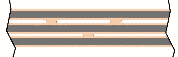
Figure 2. Chemical forces exist between graphite fibers due the sizing (coating).
Temperature Limitations
Further to the chemical forces binding fibers, the application of sizing to fibers poses another issue in graphite fiber thermal straps, that of upper temperature limitation. If graphite fiber thermal straps are exposed to a temperature above 60°C, such as during vacuum bakeout, the stiffness increases exponentially. While the exact mechanism for this affect has not been investigated in detail, it is believed that the sizing softens (possibly as it goes through the glass transition temperature) and this promotes even higher chemical reactivity and bonding between adjacent fibers. Once this happens, working the strap can result in improved range of motion, but it is not clear if bonds or actual fibers are being broken in the attempt to recover some flexibility.
Since many integrated space systems benefit from vacuum baking in the 100°C range to outgas water, this property of graphite fiber thermal straps can be extremely compromising.
Water and Graphite Fiber Lubricity
Outgassing water and other volatile constituents in space systems is critical so that molecular migration does not result in contamination on sensitive surfaces such as optics, sensors, or thermal control features. Graphite, however, achieves lubricity from the uptake of water vapor; without water, graphite is quite abrasive. The figure below shows how just a small amount of water vapor (or lack of) can greatly impact the wear rate between adjacent graphite surfaces.
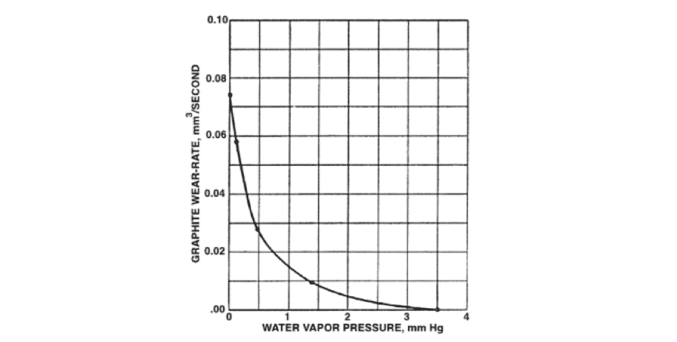
Figure 3. Wear rate in graphite due lubricity dependence on water absorption. (Courtesy of the Modern Tribology Handbook)
In the graphite fiber thermal strap, where there are potentially millions of fibers that need to move or slide relative to each other when the strap is flexed, it’s an obvious concern that stiffness greatly increases in the absence of water. If flexibility is shown and measured in the ambient laboratory environment where water vapor is present, what will be the behavior in the dry gas-purged environment of the launch fairing or in the vacuum of space? Certainly, the strap will become stiffer, but the extent is not really known unless the specific environmental measurement is made, and that can be a costly and risky proposition. In the end, the result is elevated risk to damage either the graphite fiber thermal strap or the equipment that it is mounted to when induced loads result in much larger forces than the design limit.
Coming Next……
We summarize the many limitations and risks associated with using pyrolytic graphite fiber in the construction of thermal straps and discuss how we at Thermal Space developed our Thermal LyNX® thermal straps with the motivation to mitigate risk in each identified and documented area.